Ford Mustang GT3
用户手册Ford Mustang GT3
User Manual
亲爱的 iRacing 用户:
恭喜您购买 Ford Mustang GT3!iRacing 全体成员感谢您的支持以及对我们产品的认可。我们致力于提供极致的模拟赛车体验,也希望您驾驶新车时能在赛道上尽享激情!
本指南将说明如何充分发挥新车的性能,涵盖从赛道外的车辆设置调整,到驾驶时在座舱内看到的各种信息。希望本指南能帮助您快速上手。
再次感谢您的购买,我们赛道上见!
DEAR iRACING USER,
Congratulations on your purchase of the Ford Mustang GT3! From all of us at iRacing, we appreciate your support and your commitment to our product. We aim to deliver the ultimate sim racing experience, and we hope that you’ll find plenty of excitement with us behind the wheel of your new car!
The following guide explains how to get the most out of your new car, from how to adjust its settings off of the track to what you’ll see inside of the cockpit while driving. We hope that you’ll find it useful in getting up to speed.
Thanks again for your purchase, and we’ll see you on the track!
技术规格TECH SPECS
底盘CHASSIS
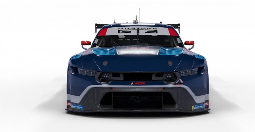
前后悬架均采用长短臂双叉臂结构
| 规格 | 数值 |
|---|---|
| 车长 | 4968 mm / 195.5 in |
| 车宽 | 2043 mm / 80.5 in |
| 轴距 | 2777 mm / 109 in |
| 干重 | 1315 kg / 2900 lbs |
| 含车手湿重(含油液) | 1479 kg / 3260 lbs |
SHORT-LONG ARM DOUBLE WISHBONE FRONT AND REAR SUSPENSION
| Specification | Value |
|---|---|
| Length | 4968mm / 195.5in |
| Width | 2043mm / 80.5in |
| Wheelbase | 2777mm / 109in |
| Dry Weight | 1315kg / 2900lbs |
| Wet Weight with Driver (Including Fluids) | 1479kg / 3260lbs |
动力单元POWER UNIT
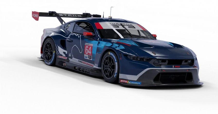
自然吸气 V8 发动机
| 规格 | 数值 |
|---|---|
| 排量 | 5.4 升 / 327 CID |
| 转速上限 | 8250 RPM |
| 扭矩 | 431 lb-ft / 584 Nm |
| 功率 | 516 bhp / 385 kW |
NATURALLY ASPIRATED V8
| Specification | Value |
|---|---|
| Displacement | 5.4 Liters / 327CID |
| RPM Limit | 8250RPM |
| Torque | 431lb-ft / 584Nm |
| Power | 516bhp / 385kW |
简介INTRODUCTION
本指南旨在帮助您深入理解车库中可用的底盘设置选项,以便按照个人偏好调校车辆。
不过,在深入调整底盘之前,最好先熟悉车辆和赛道。为此,我们为这些赛车经常使用的各条赛道提供了基准设置。要载入基准设置,只需打开“车库”,单击“iRacing 设置”,然后为所选赛道选择合适的设置。如果某条赛道没有专用基准设置,可以选择特性相近赛道的设置作为起点。
选择合适的设置后,请驶上赛道并专注于跑出平顺且稳定的圈次,找准正确的赛车线,同时在连续多圈中观察轮胎磨损和操控趋势。
The information found in this guide is intended to provide a deeper understanding of the chassis setup adjustments available in the garage, so that you may use the garage to tune the chassis setup to your preference.
Before diving into chassis adjustments, though, it is best to become familiar with the car and track. To that end, we have provided baseline setups for each track commonly raced by these cars. To access the baseline setups, simply open the Garage, click iRacing Setups, and select the appropriate setup for your track of choice. If you are driving a track for which a dedicated baseline setup is not included, you may select a setup for a similar track to use as your baseline.
After you have selected an appropriate setup, get on track and focus on making smooth and consistent laps, identifying the proper racing line and experiencing tire wear and handling trends over a number of laps.
快速上手GETTING STARTED
进入车辆后,只需按下“升挡”按钮挂入挡位,再踩下油门踏板即可起步。本车采用序列式变速箱,升挡和降挡均无须操作离合器。不过,降挡保护会在系统判断当前车速相对于目标挡位过高、可能造成发动机损坏时阻止降挡;此时,降挡指令会被直接忽略。
Once you load into the car, getting started is as easy as selecting the “upshift” button to put it into gear, and hitting the accelerator pedal. This car uses a sequential transmission and does not require a clutch input to shift in either direction. However the car’s downshift protection will not allow you to downshift if it feels you are traveling too fast for the gear selected and would incur engine damage. If that is the case, the gear change command will simply be ignored.
载入 iRacing 设置LOADING AN iRACING SETUP
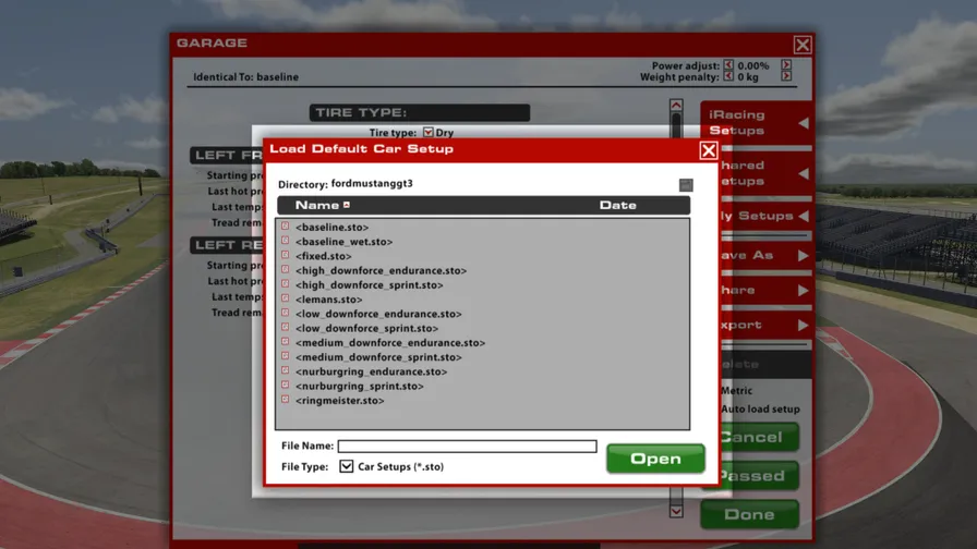
进入比赛会话后,车辆会自动载入 iRacing 基准设置 <baseline.sto>。如果您希望使用 iRacing 针对不同条件预制的其他设置,可以依次单击“车库 > iRacing 设置 >”,再选择符合需求的设置。
如需自定义设置,只需在车库中完成所需修改,然后单击“应用”。若要保存设置供日后使用,请单击右侧的“另存为”,为修改后的设置命名并保存。要查看所有个人设置,请单击车库右侧的“我的设置”。
如需与另一位车手或会话中的所有人共享设置,可以单击车库右侧的“共享”。
如果其他车手正在与您共享设置,也可以在车库右侧的“共享设置”中找到该设置。
Upon loading into a session, the car will automatically load the iRacing Baseline setup <baseline.sto>. If you would prefer one of iRacing’s pre-built setups that suit various conditions, you may load it by clicking Garage > iRacing Setups > and then selecting the setup to suit your needs.
If you would like to customize the setup, simply make the changes in the garage that you would like to update and click apply. If you would like to save your setup for future use click “Save As” on the right to name and save the changes. To access all of your personally saved setups, click “My Setups” on the right side of the garage.
If you would like to share a setup with another driver or everyone in a session, you can select “Share” on the right side of the garage to do so.
If a driver is trying to share a setup with you, you will find it under “Shared Setups” on the right side of the garage as well.
仪表页面DASH PAGES
Ford Mustang GT3 配备数字显示屏,提供三个显示页面。
The Ford Mustang GT3 features a digital display with three display pages.
比赛RACE
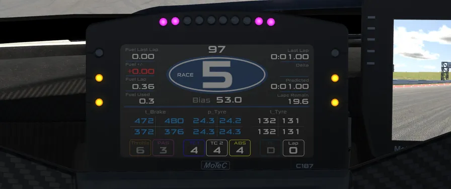
上半区
| 字段 | 说明 |
|---|---|
| Fuel Last Lap | 上一圈消耗的燃油量;单位取决于车库中选择的计量制式。 |
| Fuel +/- | 相对于目标值的燃油消耗差。系统根据若干圈的平均燃油消耗生成每圈预期用量,再与实际用量比较,此处显示二者之差。 |
| Fuel Lap | 当前圈已经消耗的燃油量,实时更新。 |
| Fuel Used | 自驶离维修区以来消耗的燃油量。 |
| Speed | 车速显示在顶部、挡位指示器上方。 |
| Gear Indicator | 当前选择的变速箱挡位,显示在屏幕中央的蓝色椭圆内。 |
| Bias | 当前前轴制动力分配百分比。 |
| Last Lap | 上一完成圈的圈速。 |
| Delta | 当前圈与本次会话最佳圈之间的实时圈速差。 |
| Predicted | 当前圈的预计圈速。 |
| Laps Remain | 按当前剩余燃油量预计可行驶的圈数。 |
下半区
| 字段 | 说明 |
|---|---|
| t_Brake | 制动盘温度。制动盘温度较低时显示蓝色,处于良好工作范围时显示白色。 |
| p_Tyre | 轮胎气压。胎压过低时显示蓝色,处于最佳范围时显示白色,过高时显示红色。 |
| t_Tyre | 实时轮胎胎体温度。与胎压相同,胎温过低时显示蓝色,过热时显示红色,处于最佳温度窗口时显示白色。 |
| Throttle | 当前油门映射设置。 |
| TC1 & TC2 | 当前牵引力控制级别设置;在 iRacing 车辆模型中二者联动。 |
| ABS | 当前防抱死制动系统设置。 |
| Laps | 本次会话已完成的圈数。 |
UPPER HALF
| Field | Description |
|---|---|
| Fuel Last Lap | The amount of fuel used in the previous lap, with units displayed based on the measuring system selected in the garage. |
| Fuel +/- | Fuel delta against a target value. This target value is generated based on average fuel usage over a set of laps as an expected usage per lap, to which the actual usage is compared against. The difference between the expected and the actual usage is displayed here. |
| Fuel Lap | The amount of fuel used in the current lap, updated live |
| Fuel Used | Amount of fuel used since leaving the pits |
| Speed | The vehicle’s speed is shown at the top, above the gear indicator |
| Gear Indicator | The currently-selected transmission gear is shown in the center of the screen within the blue oval. |
| Bias | Current % front brake bias setting. |
| Last Lap | Lap time for the previously completed lap |
| Delta | Live time difference between the current lap and the session best lap |
| Predicted | The estimated lap time for the current lap |
| Laps Remain | Number of laps remaining with the current amount of fuel |
LOWER HALF
| Field | Description |
|---|---|
| t_Brake | Brake rotor temperatures, shown in blue if the rotors are cool and white when the temperatures are in a good operating range |
| p_Tyre | Tire pressure. Shown in blue if the tire is underinflated, white if the tire pressure is in the optimum range, and red if the tire is overinflated. |
| t_Tyre | Live tire carcass temperatures. Like the pressures, these are color coded to show tires that are too cold in blue, red if overheated, and white if the tire is in the optimal temperature window |
| Throttle | Current throttle map setting |
| TC1 & TC2 | Current Traction Control level settings (in the iRacing model, these are linked) |
| ABS | Current Anti-lock Brake System setting |
| Laps | Number of completed laps in the current session |
比赛 2RACE 2
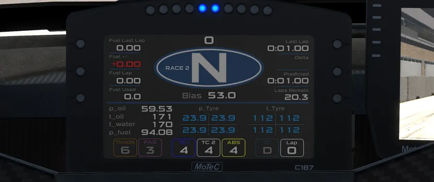
“比赛 2”页面与“比赛 1”页面相同,但制动器温度显示会替换为发动机信息。
| 字段 | 说明 |
|---|---|
| p_Oil | 机油压力。 |
| t_Oil | 发动机油温。 |
| t_Water | 发动机冷却液温度。 |
| p_Fuel | 燃油系统压力。 |
The Race 2 page is the same as the Race 1 page, except the Brake Temperature display is swapped out for engine information.
| Field | Description |
|---|---|
| p_Oil | Oil pressure. |
| t_Oil | Engine oil temperature |
| t_Water | Engine cooling water temperature |
| p_Fuel | Fuel system pressure |
排位QUALI
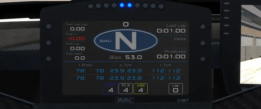
“排位”页面与“比赛”页面相同,但不显示油门映射和剩余圈数。
The “Quali” page is the same as the Race page but with the Throttle Map and Laps Remaining values removed.
维修区限速器PIT SPEED LIMITER
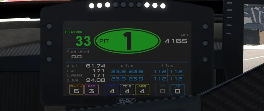
启用维修区道路限速器后,显示屏会切换为专用布局:左侧显示车速,右侧显示发动机转速,挡位指示椭圆则根据车速采用不同颜色(车速符合规定时为绿色,超过维修区限速时为红色)。换挡提示灯也会变为六盏闪烁的白灯,表示系统已启用。
Whenever the pit road speed limiter is active the display will change to a special format with vehicle speed on the left, RPM on the right, and the Gear Indicator oval color-coded based on the vehicle speed (Green for legal speed, Red when above the pit road speed limit). The shift lights will also change to six flashing white lights to indicate the system is active.
换挡提示灯SHIFT LIGHTS
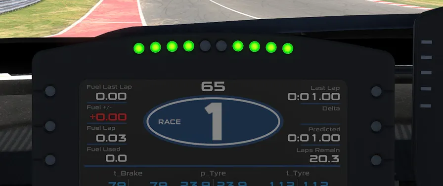
数字显示屏顶部设有一组 LED 换挡提示灯,帮助车手在加速时判断升挡时机。随着发动机转速升高,提示灯会从显示屏外侧向内侧依次亮起;达到理想换挡转速时,所有提示灯都会变为蓝色。
The top of the digital display has a set of LED shift lights to help the driver know when to upshift while accelerating. As RPM increases the lights will illuminate from the outside to the inside of the display, with all lights turning blue when the ideal shift point has been reached.
车轮抱死指示灯WHEEL LOCK INDICATORS
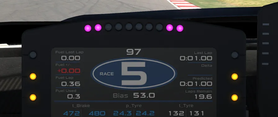
系统检测到抱死时,显示屏上方及两侧的 LED 指示灯会亮起,用于识别抱死车轮及抱死严重程度。前轮抱死由显示屏顶部的紫色 LED 表示,后轮抱死由显示屏侧面的黄色 LED 表示;每个车轮对应显示屏的相同侧(例如左侧黄色 LED 亮起表示左后轮抱死)。抱死越严重,亮起的指示灯越多:一盏 LED 表示轻微抱死,三盏 LED 表示车轮已经完全抱死。
Whenever a lockup is detected, LED indicator lights above and on either side of the display will illuminate to identify which wheel is locked up and how severe the lockup is. Front wheel lockups are indicated by purple LEDs on the top of the display, rear wheel lockups are indicated by yellow LEDs on the side of the display, with each wheel corresponding to the side of the display (ex. The Left-Rear is locked when the yellow LEDs on the left are illuminated). More lights are illuminated as lockup severity increases, with one LED being a mild lockup and three LEDs indicating a wheel is completely locked.
高级设置选项ADVANCED SETUP OPTIONS
本节面向希望深入了解车辆各项设置的高级用户。调整以下参数并非必要,而且可能显著改变车辆的操控特性。建议所有调整都采用循序渐进的方式,每次只更改一个变量,并在继续调整前先测试效果。
This section is aimed toward more advanced users who want to dive deeper into the different aspects of the vehicle’s setup. Making adjustments to the following parameters is not required and can lead to significant changes in the way a vehicle handles. It is recommended that any adjustments are made in an incremental fashion and only singular variables are adjusted before testing changes.
轮胎与空气动力学TIRES & AERO
轮胎设置TIRE SETTINGS
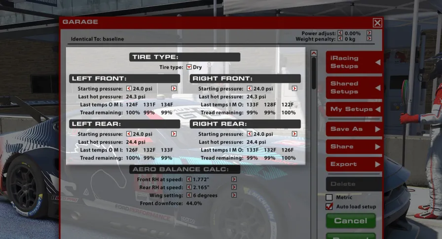
轮胎类型
选择车辆载入赛道时安装的轮胎类型。干地胎(即光头胎)用于干燥比赛条件,湿地胎则用于降雨和湿滑赛道条件。
起始胎压
车辆载入赛道时的轮胎气压。较低胎压可提供更多抓地力,但会产生更大的滚动阻力,升温也更快。较高胎压的响应感略强、滚动阻力更小,但抓地力会降低。通常,高速赛道更适合较高胎压;在更强调机械抓地力的低速赛道上,较低胎压表现更好。
上次热态胎压
车辆完成一个赛道行驶阶段并返回车库后,轮胎气压会显示为热态胎压。冷、热态胎压的差值有助于判断各条轮胎在赛道上的负荷与工作强度。工作量更大的轮胎会产生更大的胎压升幅;留意哪些轮胎升压更多,并通过调整冷态胎压进行补偿,对于优化轮胎性能至关重要。
上次胎温
车辆返回车库后,会显示轮胎胎体温度(在胎面内部测量)。这些温度可以有效判断各条轮胎在赛道上承受的工作量或负荷。内、外侧温差可用于调整单轮定位;中央温度与外侧温度的对比则有助于调整胎压。
剩余胎面厚度
胎温下方以新胎百分比显示剩余胎面厚度。这些数值适合判断一套轮胎还能行驶多远才需要更换,但不像胎温那样能够直接反映轮胎工作不足或过度工作的状态。
TIRE TYPE
Selects which type of tire is installed on the car when loaded into the world. Dry, or slick, tires are used for dry racing conditions while Wet tires are intended for rain and wet track conditions.
STARTING PRESSURE
The air pressure in the tires when the car is loaded into the world. Lower pressures will provide more grip but will produce more rolling drag and build temperature faster. Higher pressures will feel slightly more responsive and produce less rolling drag, but will result in less grip. Generally, higher pressures are preferred at tracks where speeds are higher while lower pressures work better at slower tracks where mechanical grip is important.
LAST HOT PRESSURE
When the car returns to the garage after an on-track stint, the tire pressure will be displayed as Hot Pressure. The difference between cold and hot pressure is a good way to see how tires are being loaded and worked while on track. Tires seeing more work will build more pressure, and paying attention to which tires are building more pressure and adjusting cold pressure to compensate can be crucial for optimizing tire performance.
LAST TEMPS
The tire carcass temperatures (measured within the tread) are displayed after the car returns from the track. These temperatures are an effective way to determine how much work or load a given tire is experiencing while on track. Differences between the inner and outer temperatures can be used to tune individual wheel alignment and the center temperatures can be compared to the outer temperatures to help tune tire pressure.
TREAD REMAINING
The amount of tread on the tire, displayed as a percentage of a new tire, is shown below the tire temperatures. These values are good for determining how far a set of tires can go before needing to be replaced, but don’t necessarily indicate an under- or over-worked tire in the same way temperatures will.
空气动力学平衡计算器AERO BALANCE CALC.
空气动力学平衡计算器用于帮助理解调整尾翼设置及前后车高时,空气动力学平衡会如何变化。请务必注意,此处显示的前后车高数值不会对车辆本身产生任何机械调整,但在此更改尾翼位置会实际应用到车辆上。本计算器仅作为参考工具使用。
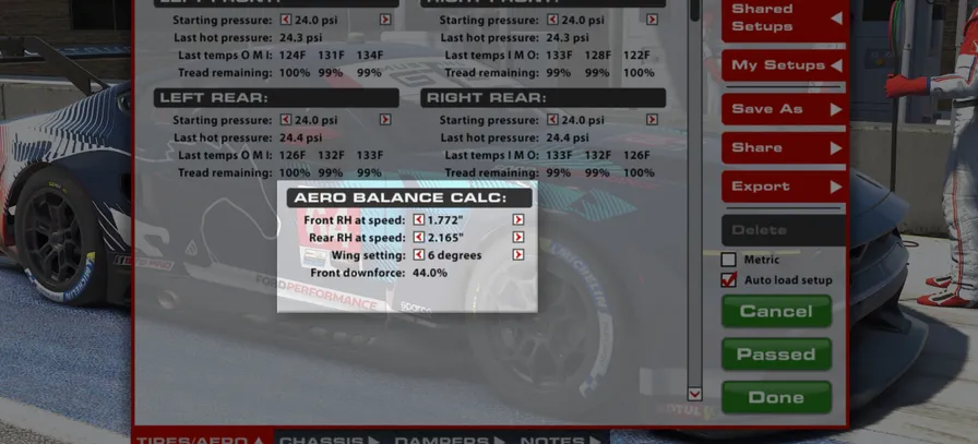
动态前车高
动态车高(RH)用于向空气动力学计算器提供计算时参考的车高。使用计算器时,通过遥测确定车辆在赛道任意位置的前车高,然后将该数值输入“动态前车高”设置。建议使用左前与右前车高的平均值;与只使用单侧车高相比,该数值能更准确地反映当前空气动力学平台姿态。
动态后车高
动态车高(RH)用于向空气动力学计算器提供计算时参考的车高。使用计算器时,通过遥测确定车辆在赛道任意位置的后车高,然后将该数值输入“动态后车高”设置。建议使用左后与右后车高的平均值;与只使用单侧车高相比,该数值能更准确地反映当前空气动力学平台姿态。
尾翼设置
尾翼设置指尾翼的相对攻角。尾翼是效力强大的空气动力学部件,会显著影响车辆产生的总下压力(以及阻力),同时随着设置增大使空气动力学平衡向后移动。增大尾翼设置可提升中高速弯中的整体过弯抓地能力,但也会降低直线速度。调整尾翼设置时,应同时考虑前后车高,尤其是二者之差,也就是“前后倾角”。要维持相同的整体空气动力学平衡,增大尾翼角度时需要同步增大车辆的前后倾角。
空气动力学计算器中的尾翼设置与底盘页面“后部”章节中的尾翼设置直接联动,更改其中一项会自动更改另一项。
前轴下压力占比
该数值显示计算器中指定的尾翼与车高组合下,作用于前轴的下压力占总下压力的比例。它只代表这组参数在当前瞬间的空气动力学平衡。可在弯道或赛段的多个位置分别取值,从而了解制动、稳态过弯和出弯加速等不同状态下空气动力学平衡的变化。前轴占比越高,车辆在中高速弯越容易出现转向过度。
The Aero Balance Calc is a tool provided to aid in understanding the shift in aerodynamic balance associated with adjustment of the rear wing setting and front and rear ride heights. It is important to note that the values for front and rear ride height displayed here DO NOT result in any mechanical changes to the car itself, however, changes to the rear wing position here WILL be applied to the car. This calculator is a reference tool ONLY.
FRONT RH AT SPEED
The Ride Height (RH) at Speed is used to give the Aero Calculator heights to reference for aerodynamic calculations. When using the aero calculator, determine the car’s Front Ride height via telemetry at any point on track and input that value into the “Front RH at Speed” setting. It is advisable to use an average value of the LF and RF ride heights as this will provide a more accurate representation of the current aero platform rather than using a single corner height.
REAR RH AT SPEED
The Ride Height (RH) at Speed is used to give the Aero Calculator heights to reference for aerodynamic calculations. When using the aero calculator, determine the car’s Rear Ride height via telemetry at any point on track and input that value into the “Front RH at Speed” setting. It is advisable to use an average value of the LR and RR ride heights as this will provide a more accurate representation of the current aero platform rather than using a single corner height.
WING SETTING
The wing setting refers to the relative angle of attack of the rear wing, this is a powerful aerodynamic device which has a significant impact upon the total downforce (and drag) produced by the car as well as shifting the aerodynamic balance of the car rearwards with higher settings. Increasing the rear wing setting results in more total cornering grip capability in medium to high speed corners but will also result in a reduction of straight line speed. Rear wing setting should be adjusted in conjunction with front and rear ride heights, specifically the difference between front and rear ride heights known as ‘rake’. To retain the same overall aerodynamic balance it is necessary to increase the rake of the car when increasing the rear wing angle.
The Wing Setting value in the Aero Calculator section is tied directly to the Wing Setting in the Chassis page’s Rear section. Changing one will automatically change the other.
FRONT DOWNFORCE
This value displays the proportion of downforce acting at the front axle for the given wing and ride height combination set within the calculator parameters. This value is an instantaneous representation of your aero balance at this exact set of parameters and it can be helpful to pick multiple points around a corner or section of track to understand how the aerodynamic balance is moving in differing situations such as braking, steady state cornering and accelerating at corner exit. A higher forwards percentage will result in more oversteer in mid to high speed corners.
底盘CHASSIS
前部/制动系统FRONT / BRAKES
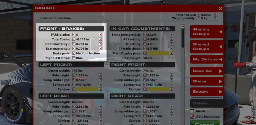
前防倾杆刀片
可调整防倾杆(ARB)刀片(或摆臂)来调节悬架的侧倾刚度。此选项改变防倾杆刀片的朝向,并以数字表示以便操作:1 为最软,数值逐步增加时刀片刚度也随之提高,5 为最硬。较硬的刀片设置会提高前轴侧倾刚度并导致更多转向不足;较软的设置会降低前轴侧倾刚度并减轻转向不足。
总前束
从上方观察时,前束角是车轮相对于底盘中心线的夹角。车轮前缘比后缘更靠近中心线称为正前束,反之则称为负前束。在前轴增加负前束会提高内侧轮胎的滑移并降低直线稳定性;增加正前束则会减少滑移并提高直线稳定性。
前制动主缸
改变前制动主缸尺寸可以调整前制动卡钳的管路压力。较大的主缸会降低前制动管路压力,使制动力分配向后移动,并增加锁死前轮所需的踏板力;较小的主缸会提高前制动管路压力,使制动力分配向前移动,并减少锁死前轮所需的踏板力。
后制动主缸
改变后制动主缸尺寸可以调整后制动卡钳的管路压力。较大的主缸会降低后制动管路压力,使制动力分配向前移动,并增加锁死后轮所需的踏板力;较小的主缸会提高后制动管路压力,使制动力分配向后移动,并减少锁死后轮所需的踏板力。
制动片
可通过制动片配方改变车辆的制动表现。“低”设置摩擦力最低,会降低制动效能,但制动力最容易细腻调制;“中”和“高”设置提供更高摩擦力、增强制动效能,但制动力的可调制空间最小。
夜间 LED 灯带
更改后窗顶部 LED 灯带的颜色。共有七种颜色可选,帮助在夜间或降雨条件下识别赛车,也可完全关闭灯带。所有设置均不会影响车辆性能。
FARB BLADES
The Anti-Roll Bar (ARB) Blades (or arms) can be adjusted to tune the suspension roll stiffness. This option changes the orientation of the ARB blades and are given numerical values for simplicity, with 1 being the softest option and the blades becoming stiffer as the value is increased to the maximum setting of 5. Stiffer blade settings will increase front roll stiffness and induce understeer while softer blade settings will reduce front roll stiffness and reduce understeer.
TOTAL TOE-IN
Toe is the angle of the wheel, when viewed from above, relative to the centerline of the chassis. Toe-in is when the front of the wheel is closer to the centerline than the rear of the wheel, and Toe-out is the opposite. On the front end, adding toe-out will increase slip in the inside tire and decrease straight-line stability while adding toe-in will reduce the slip and increase straight-line stability.
FRONT MASTER CYLINDER
The Front Brake Master Cylinder size can be changed to alter the line pressure to the front brake calipers. A larger master cylinder will reduce the line pressure to the front brakes, which will shift the brake bias rearwards and increase the pedal effort required to lock the front wheels. A smaller master cylinder will increase brake line pressure to the front brakes, shifting brake bias forward and reducing required pedal effort to lock the front wheels.
REAR MASTER CYLINDER
The Rear Brake Master Cylinder size can be changed to alter the line pressure to the rear brake calipers. A larger master cylinder will reduce the line pressure to the rear brakes, which will shift the brake bias forwards and increase the pedal effort required to lock the rear wheels. A smaller master cylinder will increase brake line pressure to the rear brakes, shifting brake bias rearward and reducing required pedal effort to lock the rear wheels.
BRAKE PADS
The vehicle’s braking performance can be altered via the Brake Pad Compound. The “Low” setting provides the least friction, reducing the effectiveness of the brakes but allowing the most modulation, while “Medium” and “High” provide more friction and increase the effectiveness of the brakes but allow the least modulation.
NIGHT LED STRIPS
Changes the color of the LED light strip at the top of the rear window. Seven color options are available to assist with car identification in nighttime or raining conditions as well as a setting to turn off the lights entirely, with no setting influencing the car’s performance.
车内调整IN-CAR ADJUSTMENTS
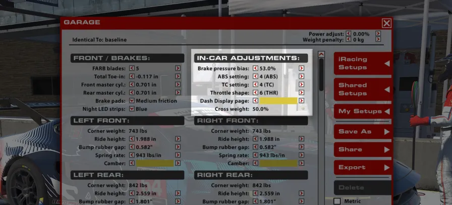
制动力分配
制动力分配表示传递至前制动器的制动力百分比。数值高于 50% 时,前制动管路压力相对于后制动管路更高,制动平衡会向前移动,前轮更容易抱死,但车辆在制动区内可能更稳定。应结合车手偏好和赛道条件进行调整,以获得当前情境下的最佳制动表现。
ABS 设置
车辆当前使用的 ABS 映射。共有 12 个挡位:挡位 1 为关闭,挡位 2 的干预/辅助最低,挡位 12 的辅助最高。建议干地使用 2 至 7,湿地使用 8 至 12。提高干预可降低制动时发生抱死的概率并缩短抱死持续时间;但若相对于可用抓地力设置过高,也可能延长制动距离。
牵引力控制设置
牵引力控制开关的位置决定 ECU 在后轮空转时削减发动机扭矩的积极程度。共有 12 个挡位:设置 2 至 12 从最低干预/灵敏度(挡位 2)逐步增加至最高干预/灵敏度(挡位 12),挡位 1 则完全关闭牵引力控制。与 ABS 设置相同,建议干地使用 2 至 7,湿地使用 8 至 12。提高干预可减少车轮空转和后胎磨损,但若牵引力控制过度削减发动机扭矩、抑制出弯加速,也可能降低整体性能。
油门曲线
油门曲线设置决定发动机扭矩输出相对于油门踏板位置的线性程度。共有 10 个设置。设置 6 为完全线性,即给定百分比的油门输入会产生相近百分比的最大扭矩(例如 25% 油门 = 25% 扭矩)。设置 1 至 5 的油门映射更温和,踏板输入较小时灵敏度较低、输入较大时灵敏度较高。设置 7 至 10 更激进,踏板输入较小时油门更灵敏、输入较大时则较不灵敏。
仪表显示页面
更改当前选择的数字仪表页面。本手册前述仪表配置章节介绍了三个可选页面。
对角配重
车库中右前轮与左后轮载荷之和占车辆总重的百分比。对于非椭圆赛道,在其他底盘设置左右对称的前提下,50.0% 通常为最佳值,可使车辆在左右弯中呈现对称的操控特性。高于 50% 的对角配重会使车辆在左弯中更容易转向不足、在右弯中更容易转向过度。可通过调整车辆各轮的弹簧座偏移量来改变对角配重。
BRAKE PRESSURE BIAS
Brake Bias is the percentage of braking force that is being sent to the front brakes. Values above 50% result in greater pressure in the front brake line relative to the rear brake line which will shift the brake balance forwards increasing the tendency to lock up the front tyres but potentially increasing overall stability in braking zones. This should be tuned for both driver preference and track conditions to get the optimum braking performance for a given situation.
ABS SETTING
The current ABS map the car is using. Twelve positions are available: Position 1 is Off. Position 2 has the least intervention/support, Position 12 has the most support. Positions 2-7 are recommended for use in dry conditions while 8-12 are best for wet conditions. More intervention reduces the possibility of and the duration of lockups during braking but can result in longer braking distances if the system is set too high for the amount of available grip.
TC SETTING
The position of the traction control switch determines how aggressively the ECU cuts engine torque in reaction to rear wheel spin. Twelve positions are available: Settings 2-12 range from least intervention/sensitivity (Position 2) to the highest intervention/ sensitivity (position 12) while position 1 disables the traction control completely. Like the ABS settings, options 2-7 are recommended for dry conditions and 8-12 are for wet conditions. More intervention will result in less wheelspin and less rear tire wear but can reduce overall performance if the traction control is cutting engine torque too aggressively and stunting corner exit acceleration.
THROTTLE SHAPE
The Throttle Shape setting will adjust how linear the torque delivery is based on the throttle pedal position. There are 10 Settings. Setting 6 is purely linear, with a given percent of throttle delivering a similar percentage of max torque (25% throttle = 25% torque). Settings 1-5 result in a less-aggressive throttle map, with low pedal inputs being less sensitive but higher inputs being more sensitive. Settings 7-10 are more aggressive, with a more sensitive throttle at low input values but less sensitive throttle at high input values
DASH DISPLAY PAGE
Changes the currently selected digital dash page. Three options are available as previously described in the dash configuration section of this manual.
CROSS WEIGHT
The percentage of total vehicle weight in the garage acting across the right front and left rear corners. A setting of 50.0% is generally optimal for non-oval tracks as this will produce symmetrical handling in both left and right hand corners providing all other chassis settings are symmetrical. Higher than 50% cross weight will result in more understeer in left hand corners and increased oversteer in right hand corners. Cross weight can be adjusted by making changes to the spring perch offsets at each corner of the car.
前轮设置FRONT CORNERS
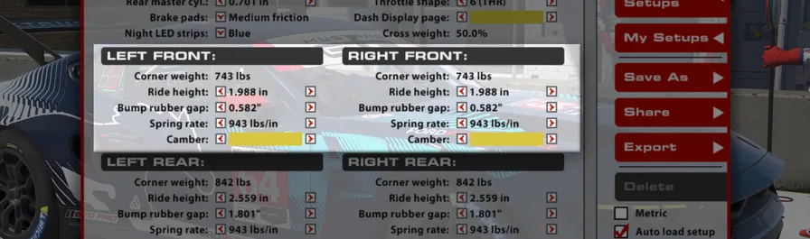
单轮载荷
车辆在车库中静止时,各车轮承受的载荷。合理分配各轮载荷,对于针对特定赛道和条件优化车辆至关重要。单轮载荷和对角配重均通过各轮车高设置进行调整。
车高
地面到前轴中心线处车辆底板的距离。车高可直接影响车辆的空气动力学性能和机械抓地力,因此是获得最佳表现的关键设置。提高前车高会减少前轴下压力和总下压力,但过弯时允许前轴发生更多横向载荷转移。相反,降低前车高会增加前轴及整车下压力,但减少前轴横向载荷转移。
限位缓冲块间隙
减振器在限位缓冲块介入前可压缩的行程。限位缓冲块介入会使悬架刚度大幅提高,从而更好地控制空气动力学平台、增强高速弯稳定性,但会降低低速弯和颠簸路面上的抓地力。数值越低,限位缓冲块越早介入;数值越高,介入越晚,悬架也能保持更好的顺应性。
弹簧刚度
此设置决定各轮所安装弹簧的刚度。较硬的弹簧可缩小高、低负荷状态间的车高变化,并通过改善平台控制带来更好的空气动力学性能;但弹簧过硬会加大轮胎载荷波动,导致机械抓地力下降。赛道越颠簸,硬弹簧的缺点通常越明显,此时使用较软弹簧反而能改善整体表现。各轮弹簧的变化会同时影响平台的侧倾和俯仰控制;调整各轮弹簧刚度时,还应考虑相应调整防倾杆,以保持原有的前后侧倾刚度分配和整体平衡。降低各轮弹簧刚度时,应提高防倾杆刚度,以维持之前的整体侧倾刚度。更换本车弹簧时,弹簧座会自动调整,以维持限位缓冲块间隙,并将车辆恢复到更换前的车高。
外倾角
外倾角是车轮相对于底盘中心的垂直夹角。车轮顶部比底部更靠近底盘中心线称为负外倾,轮胎顶部比底部更向外则称为正外倾。受悬架几何和过弯负荷影响,四个车轮通常都需要负外倾。增大负外倾角的绝对值可提高轮胎产生的横向力,但会降低制动时的纵向抓地力。外倾角过大虽然可能产生很强的过弯力,也会显著缩短轮胎寿命,因此需要在耐久性与性能之间取得平衡。增加前轮负外倾通常会增强中高速过弯时的前轴抓地力,但会损失制动性能,因此需要将制动力分配相应后移作为补偿。
CORNER WEIGHT
The weight underneath each tire under static conditions in the garage. Correct weight arrangement around the car is crucial for optimizing a car for a given track and conditions. Individual wheel weight adjustments and crossweight adjustments are made via the ride height adjustments at each corner
RIDE HEIGHT
Distance from the ground to the floor of the car at the front axle centerline. Adjusting Ride Heights is key for optimum performance, as they can directly influence the vehicle’s aerodynamic performance as well as mechanical grip. Increasing front ride height will decrease front downforce as well as decrease overall downforce, but will allow for more weight transfer across the front axle when cornering. Conversely, reducing front ride height will increase front and overall downforce, but reduce the weight transfer across the front axle.
BUMP RUBBER GAP
The distance the damper will travel before engaging the bump rubber. This will result in a much stiffer suspension and will provide better aerodynamic platform control and better stability in highspeed corners but it will reduce grip in low-speed corners and over rough surfaces. Lower values will engage the bump rubber sooner and higher values will delay engagement to allow for a more compliant suspension.
SPRING RATE
This setting determines the installed corner spring stiffness. Stiffer springs will result in a smaller variance in ride height between high and low load cases and will produce superior aerodynamic performance through improved platform control. However overly stiff springs will result in increased tire load variation which will manifest as a loss in mechanical grip. Typically the drawbacks of stiffer springs will become more pronounced on rougher tracks and softer springs in these situations will result in increased overall performance. Corner spring changes will influence both roll and pitch control of the platform and ARB changes should be considered when altering corner spring stiffnesses in order to retain the same front to rear roll stiffness and overall balance. When reducing corner spring stiffness the ARB stiffness should be increased to retain the same roll stiffness as previously. When changing springs on this car, the spring perch is automatically adjusted to maintain the bump rubber gap and return the car to the ride height it had before the change.
CAMBER
Camber is the vertical angle of the wheel relative to the center of the chassis. Negative camber is when the top of the wheel is closer to the chassis centerline than the bottom of the wheel, positive camber is when the top of the tire is farther out than the bottom. Due to suspension geometry and corner loads, negative camber is desired on all four wheels. Higher negative camber values will increase the cornering force generated by the tire, but will reduce the amount of longitudinal grip the tire will have under braking. Excessive camber values can produce very high cornering forces but will also significantly reduce tire life, so it is important to find a balance between life and performance. Increasing front camber values will typically result in increased front axle grip during mid to high speed cornering but will result in a loss of braking performance and necessitate a rearward shift in brake bias to compensate.
后轮设置REAR CORNERS
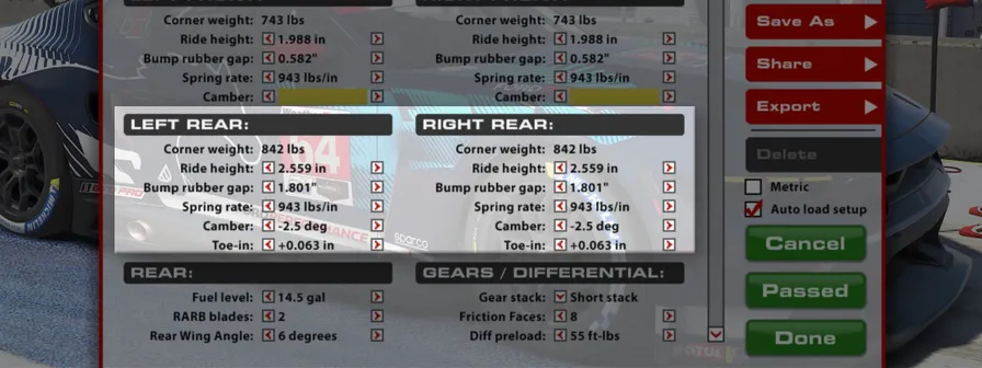
单轮载荷
车辆在车库中静止时,各车轮承受的载荷。合理分配各轮载荷,对于针对特定赛道和条件优化车辆至关重要。单轮载荷和对角配重均通过各轮车高设置进行调整。
车高
地面到后轴中心线处车辆底板的距离。提高后车高会减少后轴下压力、增加整车总下压力,并允许过弯时后轴发生更多横向载荷转移。相反,降低车高会增加后轴下压力占比、减少整车总下压力,同时降低后轴横向载荷转移。后车高是兼顾机械平衡与空气动力学平衡的关键调校项;为获得最佳表现,应根据所选后轮弹簧匹配静态后车高。Mustang 通常采用相对较小的前后倾角时表现最佳。有关最佳车高设置的更多信息,请参阅“空气动力学目标”章节。
限位缓冲块间隙
减振器在限位缓冲块介入前可压缩的行程。限位缓冲块介入会使悬架刚度大幅提高,从而更好地控制空气动力学平台、增强高速弯稳定性,但会降低低速弯和颠簸路面上的抓地力。数值越低,限位缓冲块越早介入;数值越高,介入越晚,悬架也能保持更好的顺应性。让后限位缓冲块在高负荷状态下介入,可以避免底盘触地,例如驶过代托纳椭圆赛道的倾斜弯时;但刚度提高也会使车辆在过弯或踩下油门时更难控制。
弹簧刚度
与前轴相同,较硬的弹簧可缩小高、低负荷状态间的车高变化,并通过改善平台控制带来更好的空气动力学性能,但代价是机械抓地力下降。这一缺点在低速弯出口激进加油时尤其明显;硬弹簧在此类情况下往往表现较差,在颠簸赛道上更是如此,并会导致明显的牵引力损失。弹簧刚度应根据赛道需求进行匹配,使车辆在高速和低速弯中的操控平衡保持一致。例如,若车辆高速弯转向不足、低速弯转向过度,提高后弹簧刚度可能有益。这样可以使用更低的静态后车高,减少低速过弯时后轴载荷转移,同时在高速过弯时维持甚至提高动态后车高,使空气动力学平衡前移并减少转向不足。更换本车弹簧时,弹簧座会自动调整,以维持限位缓冲块间隙,并将车辆恢复到更换前的车高。
外倾角
与前轮相同,为提高横向抓地能力,后轮也应采用较大的负外倾角;但后轮负外倾通常会略小于前轮。主要有两个原因:首先,后轮比前轮更宽;其次,后轮还必须承担驱动车辆前进的任务,因此负外倾带来的横向抓地力收益,需要与纵向牵引性能的损失相权衡。
前束
从上方观察时,前束角是车轮相对于底盘中心线的夹角。车轮前缘比后缘更靠近中心线称为正前束,反之则称为负前束。后轮通常采用正前束。增加正前束可提高直线稳定性,但会降低变向时的响应。应尽可能避免过大的正前束,因为这会增加滚动阻力并降低直线速度。调整后轮前束时请注意,此处数值分别对应每个车轮,而前轴显示的是左右合计值。因此,将后轮左右前束相加后,每个后轮单独数值的影响强度是前轴合计调整的两倍。通常建议左右前束保持一致,以避免车辆斜行或出现不对称操控;不过在莱姆罗克公园等高度不对称的赛道上,后轮前束及其他设置参数采用不对称配置可能带来性能收益。
CORNER WEIGHT
The weight underneath each tire under static conditions in the garage. Correct weight arrangement around the car is crucial for optimizing a car for a given track and conditions. Individual wheel weight adjustments and crossweight adjustments are made via the ride height adjustments at each corner.
RIDE HEIGHT
Distance from the ground to the floor of the car at the rear axle centerline. Increasing rear ride height will decrease rear downforce as well as increase overall downforce and will allow for more weight transfer across the rear axle when cornering. Conversely, reducing ride height will increase rear downforce percentage but reduce overall downforce while reducing the weight transfer across the rear axle. Rear ride height is a critical tuning component for both mechanical and aerodynamic balance considerations and static rear ride heights should be considered and matched to the chosen rear corner springs for optimal performance. Generally the Mustang will perform best with a relatively low-rake setup. See the section on Aerodynamic Targets for more information on setting optimum ride heights.
BUMP RUBBER GAP
The distance the damper will travel before engaging the bump rubber. This will result in a much stiffer suspension and will provide better aerodynamic platform control and better stability in highspeed corners but it will reduce grip in low-speed corners and over rough surfaces. Lower values will engage the bump rubber sooner and higher values will delay engagement to allow for a more compliant suspension. Engaging the bump rubbers on the rear can keep the chassis off the track in high-load situations to keep the car from bottoming out on the track, like Daytona’s oval banking, but due to the increased stiffness it can make the car more difficult to control when cornering or during throttle application.
SPRING RATE
Similar to the front axle, stiffer springs will result in a smaller variance in ride height between high and low load cases and will produce superior aerodynamic performance through improved platform control at the expense of mechanical grip. This can be particularly prominent when exiting slow speed corners with aggressive throttle application. Stiffer springs will tend to react poorly during these instances especially so on rough tracks which will result in significant traction loss. Spring stiffness should be matched to the needs of the racetrack and set such that the handling balance is consistent between high and low speed cornering. As an example case, a car which suffers from high speed understeer but low speed oversteer could benefit from an increase in rear spring stiffness. This will allow for a lower static rear height which will reduce rear weight transfer during slow speed cornering while maintaining or even increasing the rear ride height in high speed cornering to shift the aerodynamic balance forwards and reduce understeer. When changing springs on this car, the spring perch is automatically adjusted to maintain the bump rubber gap and return the car to the ride height it had before the change.
CAMBER
As with the front of the car it is desirable to run significant amounts of negative camber in order to increase the lateral grip capability; however, it is typical to run slightly reduced rear camber relative to the front. This is primarily for two reasons, firstly, the rear tires are wider compared to the fronts and secondly the rear tires must also perform the duty of driving the car forwards where benefits of camber to lateral grip become a tradeoff against reduced longitudinal (traction) performance.
TOE-IN
Toe is the angle of the wheel, when viewed from above, relative to the centerline of the chassis. Toe-in is when the front of the wheel is closer to the centerline than the rear of the wheel, and Toe-out is the opposite. At the rear of the car it is typical to run toe-in. Increases in toe-in will result in improved straight line stability and a reduction in response during direction changes. Large values of toe-in should be avoided if possible as this will increase rolling drag and reduce straight line speeds. When making rear toe changes remember that the values are for each individual wheel as opposed to paired as at the front. This means that individual values on the rear wheels are twice as powerful as the combined adjustment at the front of the car when the rear toes are summed together. Generally, it is advised to keep the left and right toe values equal to prevent crabbing or asymmetric handling behavior; however, heavily asymmetric tracks such as Lime Rock Park may see a benefit in performance from running asymmetric configurations of rear toe and other setup parameters.
后部REAR
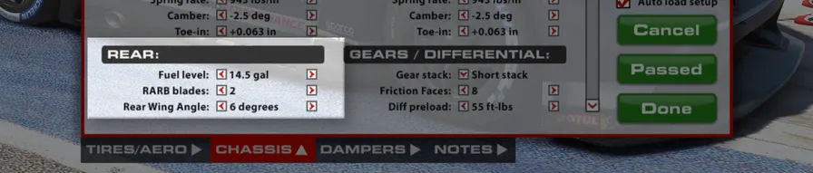
燃油量
车辆载入赛道时的燃油量。
后防倾杆刀片
可调整防倾杆(ARB)刀片(或摆臂)来调节悬架的侧倾刚度。此选项改变防倾杆刀片的朝向,并以数字表示以便操作:1 为最软,数值逐步增加时刀片刚度也随之提高,5 为最硬。较硬的刀片设置会提高后轴侧倾刚度并导致更多转向过度;较软的设置会降低后轴侧倾刚度并减轻转向过度。
尾翼角度
尾翼设置指尾翼的相对攻角。尾翼是一项会显著影响车辆总下压力(以及阻力)的空气动力学装置;角度越大,空气动力学平衡也越向后移动。增大尾翼角度可提升中高速弯中的整体过弯抓地能力,但也会降低直线速度。调整尾翼角度时,应同时考虑前后车高,尤其是二者之差,也就是“前后倾角”。要维持相同的整体空气动力学平衡,增大尾翼角度时需要同步增大车辆的前后倾角。
FUEL LEVEL
The amount of fuel in the car when loaded into the world.
RARB BLADES
The Anti-Roll Bar (ARB) Blades (or arms) can be adjusted to tune the suspension roll stiffness. This option changes the orientation of the ARB blades and are given numerical values for simplicity, with 1 being the softest option and the blades becoming stiffer as the value is increased to the maximum setting of 5. Stiffer blade settings will increase rear roll stiffness and induce oversteer while softer blade settings will reduce rear roll stiffness and reduce oversteer.
REAR WING ANGLE
The wing setting refers to the relative angle of attack of the rear wing, this is an aerodynamic device which has a significant impact upon the total downforce (and drag!) produced by the car as well as shifting the aerodynamic balance of the car rearwards with increasing angle. Increasing the rear wing angle results in more total cornering grip capability in medium to high speed corners but will also result in a reduction of straight line speed. Rear wing angle should be adjusted in conjunction with front and rear ride heights, specifically the difference between front and rear ride heights known as ‘rake’. To retain the same overall aerodynamic balance it is necessary to increase the rake of the car when increasing the rear wing angle.
齿比/差速器GEARS / DIFFERENTIAL
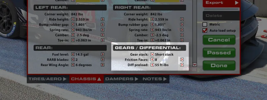
齿比组
齿比组设置会改变变速箱各前进挡齿比。共有三种选择:Short、FIA 以及 Le Mans & Daytona 通用齿比组。Short 齿比组更适合最高速度较低(<270 km/h)的高下压力赛道;FIA 齿比组更适合最高速度可达 280 km/h、速度更高的中下压力赛道;Le Mans & Daytona 齿比组则用于车速极高的低阻力赛道,且只应在勒芒和代托纳使用。
摩擦面数量
差速器内的摩擦面数量会影响保持后轴锁止所施加的总作用力。摩擦面数量相当于锁止力的倍增系数,增加摩擦面会逐步提高锁止力。例如,8 个摩擦面的锁止力是 4 个的两倍,而 4 个的锁止力又是 2 个的两倍。增加摩擦面会使车辆收油时更容易转向不足、加油时更容易转向过度;减少摩擦面则会减弱这些效果。
差速器预载
差速器预载是差速器内部恒定存在的静态锁止力,在加速和减速时均保持不变。提高差速器预载会增强差速器两侧的锁止作用,导致车辆收油时更容易转向不足,激进加油时更容易突然转向过度。提高预载还会使加油与收油之间的操控过渡更平顺,因为差速器锁止力不会降至零;这有助于减少收油转向过度,并增强车手信心。通常,当车辆在低速弯出口的驱动力明显不足,和/或在中低速弯中油门与制动转换时旋转过度,应提高差速器预载。
GEAR STACK
Gear Stack changes the forward gear ratios in the transmission. Three choices are available: Short, FIA, and a common Le Mans & Daytona. The Short gear stack is more suited to high-downforce tracks where top speeds are low (<270kph) while the FIA gear stack is better for faster, medium-downforce tracks up to 280kph. The Le Mans & Daytona gear stack is for low-drag tracks where speeds are very high, and should only be used at these two tracks.
FRICTION FACES
The number of friction faces in the differential affect how much overall force is applied to keep the rear axle locked. Treated as a multiplier, adding more faces produces increasingly more locking force. For example, 8 friction faces will have twice the locking force of 4 faces, which will have twice the force of 2 faces. Adding friction faces will induce off-throttle understeer and on-throttle oversteer, reducing friction faces will reduce these effects.
DIFFERENTIAL PRELOAD
Diff preload is a static amount of locking force present within the differential and remains constant during both acceleration and deceleration. Increasing diff preload will increase locking on both sides of the differential which will result in more understeer when off throttle and more snap oversteer with aggressive throttle application. Increasing the diff preload will also smooth the transition between on and off throttle behavior as the differential locking force will never reach zero which can be helpful in reducing lift-off oversteer and increasing driver confidence. Typically diff preload should be increased when there is noticeable loss in slow corner exit drive and/or over-rotation during transition between the throttle and brake in low to mid speed corners.
减振器——Multimatic DSSV 四路可调DAMPERS - MULTIMATIC DSSV 4-WAY
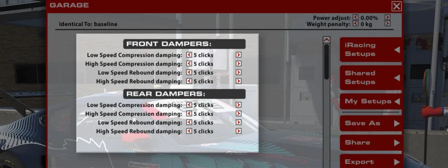
低速压缩阻尼
低速压缩阻尼(LSC)决定减振器活塞杆以较低速度运动并压缩(长度缩短)时的阻力,通常对应转向、制动、油门等车手输入以及过弯力引起的车身运动。此项采用泄流调节方式,设置 11 为最大阻尼(压缩阻力最大),0 为最小阻尼(压缩阻力最小)。增大低速压缩阻尼,会使制动、变向等瞬态动作中载荷更快地转移至车辆前部或后部,通常也会使车辆在加油时更容易转向不足。
在车辆前部,增大 LSC 会使车辆在制动及前悬架压缩时更容易转向不足。在车辆后部,增大 LSC 会提高加油时以及后悬架压缩过程中的牵引力;设置过高时,车手可能会将这种表现感受为转向不足。
高速压缩阻尼
高速压缩阻尼(HSC)影响减振器活塞杆高速运动时的表现,通常对应压过路肩或赛道表面颠簸。设置 11 为最大阻尼,0 为最小阻尼。提高高速压缩阻尼会使悬架在这些情况下更硬;降低 HSC 能让悬架更好地吸收颠簸,但可能削弱车辆在赛道上的空气动力学平台控制。在较平整的赛道上,提高高速压缩阻尼通常能改善表现;在较颠簸或路肩激进的赛道上,降低高速压缩阻尼可牺牲部分平台控制来换取更多机械抓地力。HSC 对正确控制底盘的侧倾、俯仰与升沉非常重要。
低速回弹阻尼
低速回弹阻尼(LSR)控制减振器活塞杆以较低速度伸长时的刚度,通常对应车手操作引起的车身运动。此项采用泄流调节方式,设置 11 为最大阻尼,0 为最小阻尼。较高的回弹数值会抑制减振器伸长,较低的数值则允许减振器更快伸长。较高的回弹刚度能改善空气动力学平台控制和底盘整体响应,但如果悬架在载荷减小时无法足够快地伸长,也可能导致轮胎完全失去与赛道表面的接触。
在车辆前部,提高 LSR 会使车头在加速时更长时间保持低位,但在加油或越过坡顶时可能引发转向不足。在车辆后部,提高 LSR 可在制动时稳定车辆,但设置过于激进也可能导致转向不足。
高速回弹阻尼
高速回弹阻尼(HSR)控制减振器经过颠簸和路肩后伸长时的表现。设置 11 为最大阻尼,0 为最小阻尼。较高的阻尼作用力会降低减振器伸长速度,较低数值则允许减振器更快伸长。尽管 HSR 对车手输入所引起操控变化的影响较小,但它对于底盘针对赛道路面输入作出正确的空气动力学响应非常重要。
LOW SPEED COMPRESSION
Low speed compression (LSC) affects how resistant the shock is to compression (reduction in length) when the shock is moving at relatively low speeds, usually in chassis movements as a result of driver input (steering, braking, & throttle) and cornering forces. This adjustment is a bleed adjuster where the 11 setting is maximum damping (most resistance to compression) and 0 is minimum damping (least resistance to compression). Increasing the low speed compression damping will result in a faster transfer of weight to the front or rear of the car during transient movements such as braking and direction change with increased damping usually increasing the cars tendency to understeer on throttle application.
On the front end of the car, increasing LSC will induce understeer under braking and whenever the front suspension is compressing. On the rear, more LSC will increase traction on throttle and when the rear suspension is in compression, which can be perceived as understeer in extreme cases.
HIGH SPEED COMPRESSION
High speed compression (HSC) affects the shock’s behavior at faster damper shaft speeds, usually attributed to curb strikes and bumps in the track’s surface. The 11 setting is maximum damping and 0 is the minimum. More high speed compression will cause the suspension to be stiffer in these situations, while less HSC will allow the suspension to absorb these bumps better but may hurt the aerodynamic platform around the track. At smoother tracks more high speed compression damping will typically increase performance while at rougher tracks or ones with aggressive kerbs less high speed compression damping can result in an increase in mechanical grip at the expense of platform control. HSC is important for proper roll, pitch & heave control of the chassis.
LOW SPEED REBOUND
Low speed rebound (LSR) damping controls the stiffness of the shock while extending at lower damper shaft speeds, typically during body movement as a result of driver inputs. This adjustment is a bleed adjuster where the 11 setting is maximum damping and 0 is minimum damping. Higher rebound values will resist expansion of the shock, lower values will allow the shock to extend faster. Higher rebound stiffness will result in improved platform control for aerodynamic performance and overall chassis response but can result in the tire losing complete contact with the track surface if the suspension can’t extend fast enough with reduced loads.
On the front end, higher LSR settings will hold the front of the car down longer during acceleration but can induce understeer on throttle application or over crests. On the rear of the car, more LSR will stabilize the car under braking but can induce understeer if set too aggressively.
HIGH SPEED REBOUND
High-speed rebound (HSR) controls the shock in extension after bumps and curb strikes. The 11 setting is maximum damping and 0 is the minimum. Higher forces will reduce how quickly the shock will expand, while lower values will allow the shock to extend more quickly. Despite not having as much of an effect on handling in response to driver inputs, HSR is important for proper chassis aerodynamic response to circuit inputs.
调校提示SETUP TIPS
本节旨在帮助希望深入了解车辆各项设置的用户。
This section is aimed toward helping users who want to dive deeper into the different aspects of the vehicle’s setup.
调校提示SETUP TIPS
在 iRacing 设置文件夹中可以找到多种设置:
“基准”是一套使用 100% 燃油量的设置,仅用于确保车辆能够载入赛道。因此,它应当能在任何燃油量和赛道上通过技术检查(纽博格林北环布局除外,该赛道应使用 nuburgring_sprint/endurance),但无法提供极限性能。
名称带有 ‘_wet’ 的设置已预装湿地胎,并包含适合湿地条件的调整。
名称带有 ‘_sprint’ 的设置使用 50% 燃油量,操控平衡更激进,适用于存在燃油限制或比赛时长约为 25 至 30 分钟的场合。这些设置面向正式比赛使用。
名称带有 ‘_endurance’ 的设置使用 100% 燃油量,适用于没有燃油限制和/或比赛时长约为 1 小时以上的场合。
名为 ‘fixed’ 的设置用于固定设置系列赛,与 high_downforce_sprint 设置相近。
名称带有 ‘nurburgring_’ 的设置采用 70 mm 最低车高,仅供纽博格林北环各布局使用。
虽然大多数赛道通常更偏向较高下压力,但在部分场合,减小尾翼角度、降低阻力也可能有利。作为粗略参考,可在以下赛道采用相应的下压力级别:
| 赛道 | 下压力级别 | 赛道 | 下压力级别 |
|---|---|---|---|
| 若泽·卡洛斯·帕切赛道 | 高/中 | 长滩街道赛道 | 高 |
| 蒙扎国家赛车场 | 中 | 奥舍斯莱本赛车运动场 | 高 |
| 布兰兹哈奇赛道 | 高 | 帕诺拉马山赛道 | 高/中 |
| 巴塞罗那-加泰罗尼亚赛道 | 高 | 纽博格林大奖赛赛道 | 高 |
| 马尼库尔赛道 | 高/中 | 冈山国际赛道 | 高 |
| 斯帕-弗朗科尔尚赛道 | 中 | 美洲公路赛道 | 高/中 |
| 勒芒 24 小时赛道 | 中 | 赛百灵国际赛道 | 高 |
| 代托纳国际赛道 | 低/中 | 银石赛道 | 高/中 |
| 底特律贝尔岛大奖赛赛道 | 高 | 索诺玛赛道 | 高 |
| 富士国际赛车场 | 高/中 | 弗吉尼亚国际赛道 | 高/中 |
| 匈牙利赛道 | 高 | 沃特金斯格伦国际赛道 | 高/中 |
| 印第安纳波利斯赛车场 | 中 | 拉古纳塞卡赛道 | 高 |
莱姆罗克公园赛道:高下压力
如果要驾驶表中未列出的赛道,建议先使用高下压力设置,再评估其他下压力级别。判断赛道是否可能受益于降低下压力级别时,车辆达到的最高速度是一个很有用的指标。
以下界限可作为选择最佳下压力级别的参考,但请注意,赛道设计(高速弯数量等)、海拔和环境条件也会影响判断;海拔越高、环境温度越高,通常越需要较高下压力。
| 速度 | 下压力级别 |
|---|---|
| 最高速度低于 250 km/h(155 mph) | 高下压力 |
| 最高速度为 250 至 270 km/h | 中下压力 |
| 最高速度高于 270 km/h(167 mph) | 低至最低下压力 |
In the iRacing Setups folder you will find a variety of setups:
Baseline is a 100% fuel load setup which is intended solely for loading the car. As such, this setup should always pass tech inspection at every fuel load and track (Except Nürburgring Nordschleife configurations where ‘nuburgring_sprint/endurance’ should be used) but will not provide ultimate performance.
Setups labeled ‘_wet’ have wet tyres pre-fitted and setup adjustments to suit wet conditions.
Setups labeled ‘_sprint’ have a 50% fuel load, a more aggressive balance and are intended for use where there is either a fuel limitation OR race lengths are approximately 25 to 30 minutes in length. These setups are intended to be used in competition.
Setups labeled ‘_endurance’ have a 100% fuel load and are for use where no fuel restriction is present and/or race lengths are approximately 1 hour or more in length.
The setup titled ‘fixed’ is the setup used in the fixed setup series and is similar to the high_downforce_sprint setup.
Setups labeled ‘nurburgring_’ are built with 70 mm minimum ride heights and are for use solely on Nürburgring Nordschleife configurations.
While most tracks will trend towards favoring more downforce there can be some instances where reducing rear wing angle for less drag may be beneficial. As a rough guide, you can expect the following downforce trims at the following tracks:
| Tracks | Downforce Level | Tracks | Downforce Level |
|---|---|---|---|
| Autodromo Jose Carlos Pace | High/Medium | Long Beach Street Circuit | High |
| Autodromo Nazionale Monza | Medium | Motorsports Arena Oschersleben | High |
| Brands Hatch Circuit | High | Mount Panorama Circuit | High/Medium |
| Circuit de Barcelona Catalunya | High | Nürburgring Grand-Prix-Strecke | High |
| Circuit de Nevers Magny-Cours | High/Medium | Okayama International Circuit | High |
| Circuit de Spa-Francorchamps | Medium | Road America | High/Medium |
| Circuit des 24 Heures Du Mans | Medium | Sebring International Raceway | High |
| Daytona International Speedway | Low/Medium | Silverstone Circuit | High/Medium |
| Detroit Grand Prix at Belle Isle | High | Sonoma Raceway | High |
| Fuji International Speedway | High/Medium | Virginia International Raceway | High/Medium |
| Hungaroring | High | Watkins Glen International | High/Medium |
| Indianapolis Motor Speedway | Medium | WeatherTech Raceway at Laguna Seca | High |
Lime Rock Park High
Should you wish to drive at a track not listed it is recommended to start out with the High Downforce setup first before evaluating the other downforce level options. A good indicator of if a track may benefit from a reduction in downforce trim is the maximum speed reached.
The following boundaries are suggestions for what trim level may be optimal but please note that other factors such as track design (number of high speed corners, etc), altitude and ambient conditions will also impact your decision here with higher altitude tracks and hotter ambient conditions favoring more downforce.
| Speed | Downforce Level |
|---|---|
| Max Speed under 250 km/h (155 mph) | High Downforce |
| Max Speed 250 to 270 km/h | Medium |
| Max Speed over 270 km/h (167 mph) | Low to Minimum Downforce |
空气动力学目标与调整AERODYNAMIC TARGETS AND ADJUSTMENTS
GT3 赛车对前后轴车高的微小变化都非常敏感,因此调整静态车高、各轮弹簧刚度和尾翼角度等设置时,必须将这一点纳入考虑。
可获得最大总下压力的最佳配置如下:
- 尾翼角度:+9
- 动态前车高:37.5 mm(±2.5 mm)
- 动态后车高:57.5 mm(±2.5 mm)
车高高于或低于上述目标后,总下压力都会开始下降。以最大下压力为目标时,必须考虑赛道各处的实际状态。例如,如果制动时后车高超过目标值,空气动力学平衡会向前移动,同时总下压力也会降低,形成不稳定状态。在实际驾驶中,正是这些制动阶段的因素决定了车辆能够多接近理论最大下压力目标。
可获得最低总阻力的最佳配置如下:
- 尾翼角度:+0.5
- 动态前车高:17.5 mm(±2.5 mm)
- 动态后车高:17.5 mm(±2.5 mm)
在大多数赛道上,车高很难降至足以达到这些低阻力目标,不过在代托纳等赛道上有可能做到。请记住,绝对最低车高受路面状况限制。随着车高接近上述目标,空气阻力会下降;但如果车辆开始触地,总阻力反而可能增加。还需说明的是,这套低阻力设置无论对总下压力还是操控平衡而言都不是最佳方案。
调整尾翼角度时,应采用以下配套调整来维持空气动力学平衡:
- 尾翼角度:+1
- 前车高:-1.5 mm
- 或
- 后车高:+4.0 mm
- 尾翼角度:-1
- 前车高:+1.5 mm
- 或
- 后车高:-4.0 mm
必要时也可以组合调整前后车高(例如后车高难以继续降低时)。这样在减小尾翼角度的同时,可以保留更多总下压力且不破坏平衡,但代价是空气阻力略微增加。
这些参考值只是建议目标,车辆整体平衡仍应放在首位。在某些情境下,车辆可能无法在这些目标值上获得良好平衡,此时应牺牲少量绝对性能,以换取更好的操控平衡。
- 较小尾翼角度 = 更多转向过度、更少下压力、更小阻力、更低过弯速度、更高直线速度。
- 较大尾翼角度 = 更多转向不足、更多下压力、更大阻力、更高过弯速度、更低直线速度。
GT3 cars are very sensitive to small variations in ride heights at both the front and rear axle and this must be kept in mind when making setup adjustments such as static ride heights, corner spring rates and rear wing angle.
The optimal configuration for most total downforce is as follows:
- Rear Wing Angle: +9
- Dynamic Front Ride Height: 37.5 mm (+/-2.5 mm)
- Dynamic Rear Ride Height: 57.5 mm (+/-2.5 mm)
Should you go over or under the ride height targets stated above you will begin to lose overall downforce. It is very important to consider all aspects of the track when aiming for this maximum downforce target. Consider that if the rear ride height increases beyond the target during braking, you will experience both a balance shift forwards and a loss in overall downforce resulting in a destabilizing situation. It is these braking considerations that will govern how closely you can approach this maximum in a real world situation.
The optimal configuration for the least total drag is as follows:
- Rear Wing Angle: +0.5
- Dynamic Front Ride Height: 17.5 mm (+/- 2.5 mm)
- Dynamic Rear Ride Height: 17.5 mm (+/- 2.5 mm)
For the majority of tracks, it will be difficult to achieve ride heights low enough to hit these drag targets; however, it is possible at a track such as Daytona. Please keep in mind that your absolute minimums are governed by the road surface and that while aerodynamic drag will decrease as you approach these targets, overall drag may increase if the car starts to make ground contact. It should also be stated that this low drag trim is neither optimal for total downforce nor handling balance.
When adjusting the rear wing angle, the following adjustments should be made to retain aerodynamic balance:
- Rear Wing Angle: +1
- Front Ride Height: -1.5 mm
- OR
- Rear Ride Height: +4.0 mm
- Rear Wing Angle: -1
- Front Ride Height: +1.5 mm
- OR
- Rear Ride Height: -4.0 mm
It is also possible to combine adjustments of front and rear ride height together if necessary (such as when lower rear heights cannot be easily achieved), this can result in more overall downforce being retained when reducing wing angle without detrimentally impacting the balance but at the cost of slightly increased aerodynamic drag.
These reference values are provided as targets to aim for, however, overall car balance should remain the priority. It may not be possible to achieve a good balance at these targets in certain situations and as such, you should elect to sacrifice some raw performance for a better balance.
- Lower Rear Wing Angle = More oversteer, less downforce, less drag, lower cornering speed, higher straight line speed.
- Higher Rear Wing Angle = More understeer, more downforce, more drag, higher cornering speed, lower straight line speed.
底盘调整CHASSIS ADJUSTMENTS
如果希望调整车辆的基础平衡,又不想显著改变空气动力学平台的俯仰与升沉控制,也不想调整差速器,可以使用前后可调防倾杆。
- 更硬的前防倾杆 -> 更多转向不足
- 更软的前防倾杆 -> 更多转向过度
- 更硬的后防倾杆 -> 更多转向过度
- 更软的后防倾杆 -> 更多转向不足
- 同时调软前、后防倾杆 -> 空气动力学性能下降、机械抓地力增加(适合颠簸路面)、对操作输入的响应变慢。
- 同时调硬前、后防倾杆 -> 空气动力学性能提升(适合高速长弯)、机械抓地力减少、对操作输入的响应增强。
Should you wish to adjust the underpinning balance of the car without impacting the aero platform significantly in pitch and heave, or adjusting the differential then front and rear adjustable anti-roll bars are available.
- Stiffer front ARB -> More Understeer
- Softer front ARB -> More Oversteer
- Stiffer rear ARB -> More Oversteer
- Softer rear ARB -> More Understeer
- Softer front AND rear ARB -> Reduced aerodynamic performance, more mechanical grip (good for rough surfaces) and slower response to inputs.
- Stiffer front AND rear ARB -> Increased aerodynamic performance (good for fast sweeping corners), less mechanical grip and increased response to inputs.
差速器调整DIFFERENTIAL ADJUSTMENTS
- 更多摩擦面 -> 收油时更多转向不足、加油时更多转向过度,颠簸路面和压路肩时内侧车轮更不易空转。
- 更少摩擦面 -> 收油时更少转向不足、加油时更少转向过度,颠簸路面和压路肩时内侧车轮更容易空转。通常更适合斯帕等路面平整且路肩较平的赛道。
在全油门、持续制动或纯滑行等输入扭矩较高的情况下,摩擦面数量的影响占主导地位。
预载会叠加到差速器总锁止扭矩上,相当于一个始终存在的偏置扭矩,即使输入扭矩为零也不会消失。因此,在差速器输入扭矩接近零的过渡状态下,例如松开油门和/或刚开始拖刹时,预载的影响更为显著。
- 更高预载 -> 更少收油转向过度、更高入弯稳定性、收油时更多转向不足、加油时更多转向过度。
- 更低预载 -> 更多收油转向过度、更低入弯稳定性、收油时更少转向不足、加油时更少转向过度。
- More friction faces -> More off throttle understeer, more on throttle oversteer, less inside wheelspin-up on rough surfaces and kerb strikes.
- Less friction faces -> Less off throttle understeer, less on throttle oversteer, more inside wheelspin-up on rough surfaces and kerb strikes. Typically better at tracks like Spa or those with smooth surfaces and flat kerbing.
Friction faces are dominant at high input torques such as full throttle, sustained braking or pure coastdown.
Preload is additive to the total locking torque of the differential and acts as an offset torque which is always present, even at zero input torque. This means that it is more dominant during transition behavior where the differential input torque is near zero, such as at throttle lift and/or during initial trail braking.
- More preload -> Less liftoff oversteer, more corner entry stability, more off throttle understeer, more on throttle oversteer.
- Less preload -> More liftoff oversteer, less corner entry stability, less off throttle understeer, less on throttle oversteer.